Converting a fisheye image into a panoramic or perspective projection[转]
Converting a fisheye image
Written by Paul Bourke |
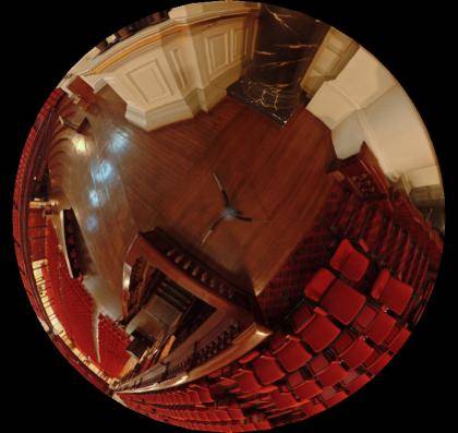 Input image example, courtesy Peter Murphy. |
A critical consideration is antialiasing, required when sampling any discrete signal. The approach here is a simple supersampling antialiasing, that is, each pixel in the output image is subdivided into a 2x2, 3x3....grid and the inverse mapping applied to the subsamples. The final value for the output pixel is the weighted average of the inverse mapped subsamples. There is a sense in which the image plane is considered to be a continuous function. Since the number of samples that are inverse mapped is the principle determinant of performance, high levels of antialiasing can be very expensive, typically 2x2 or 3x3 are sufficient especially for images captured from video in which neighbouring pixels are not independent in the first place.
Antialias: 3x3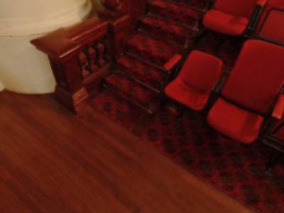 downfish2persp -cf -cf 380 353 -r 360 |
Antialias: None |
In general the jagged edges are more noticeable in features with a sharp colour/intensity boundary. The other form of aliasing that occurs because of insufficient samples of high frequency structure is less common in video material, more common in computer graphics.
Antialias: 3x3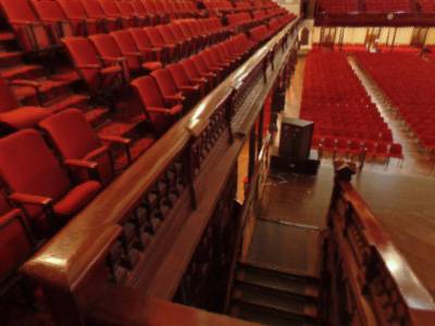 downfish2persp -cf 300 262 -r 310 -cp -90 60 -ap 90 |
Antialias: None |
The vertical aperture is automatically adjusted to match the width and height.
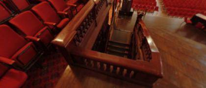 downfish2persp -a 3 -cf 380 353 -r 360 -cp 110 50 -ap 100 -w 700 -h 300 |
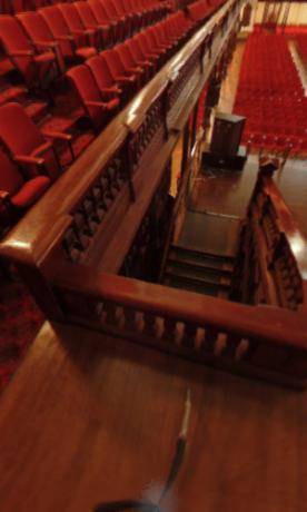 downfish2persp -a 3 -cf 380 353 -r 360 -cp 110 50 -ap 60 -w 300 -h 500 |
The center of the fisheye on the input image can be found by projecting lines along vertical structure in the scene. Where these lines intersect is a close approximation to the center of the fisheye, assuming the camera is mounted vertically.
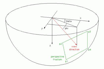
The naming conventions and axis alignment are shown below. The camera is modelled as having a position (same as fisheye camera), a view direction and an up vector which is always assumed to be in the negative z direction. The right vector is derived from these and then the up vector is recomputed to ensure an orthographic camera coordinate system. The case where the camera points straight down (along the z axis) is treated as a special case. A straightforward addition would be to allow the camera up vector to be a user option permitting cameras the roll.
To test the algorithm a fisheye rendering inside a gridded cube is a good example, see image on left below. Any perspective projection should reult in straight lines.
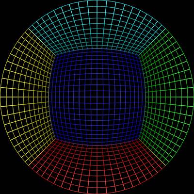 Sample input image |
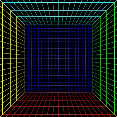 downfish2persp -a 3 -w 800 -h 800 -cp 0 90 -ap 100 |
 downfish2persp -a 3 -w 800 -h 800 -cp 40 40 -ap 60 |
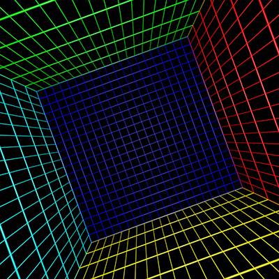 downfish2persp -a 3 -w 800 -h 800 -cp 20 90 -ap 120 |
Fisheye to perspective
Software: fish2persp
Updated: Nov 2015
The following is indended to simply convert a fisheye into a perfect pinhole perspective camera. Currently assumes the fisheye is centered, that is, the center of the fisheye is the center of the perspective view. It allows one to choose the field of view of the perspective camera, the angle of the circular fisheye, the center and radius of the fisheye circle.
Usage: fish2persp [options] fisheyeimage
Options
   -w n     perspective image width, default = 800
   -h n     perspective image height, default = 600
   -t n     aperture of perspective (degrees), default = 100
            maximum is 170 degrees
   -s n     aperture of fisheye (degrees), default = 180
   -c x y   offset of the center of the fisheye image,
            default is fisheye image center
   -r n     fisheye radius, default is half height of fisheye image
   -a n     antialiasing level, default = 1 (no antialising)
            sensible maximum 3
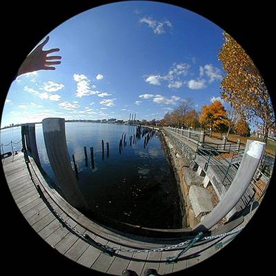 Sample input image |
 fish2persp -w 800 -h 800 -t 90 -a 3 |
A better test is to render a fisheye of a cubic structure (left below), the perspective view should consist of straight lines irrespective of the camera field of view.
 Sample input image |
 fish2persp -w 800 -h 800 -t 120 -a 3 |
Downward pointing fisheye to panoramic warping
Software: downfish2pano
Updated: Nov 2015
Usage: downfish2pano [options] fisheyeimage
Options
   -w n     panoramic image width, default = 600
   -f n     fisheye FOV, default = 180 deg
   -v n n   start and stop latitude for panoramic, default = 20...80 deg
   -t n n   start and stop longitude for panoramic, default = 0...360 deg
  -cf x y   center of the fisheye image, default is image center
   -r n     radius of the fisheye image, default is half the image width
   -a n     antialiasing level, default = 1 (no antialising)
The input image used for the following examples is the same one used above for the perspective warping. The grey regions below correspond to where the fisheye is clipped by the image rectangle, ie: the fisheye is not complete.
 downfish2pano -a 3 -cf 380 353 -r 360 |
A subset of the panoramic by choosing a longitude range.
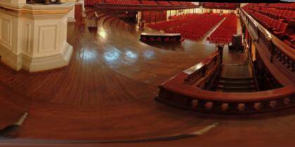 downfish2pano -a 3 -cf 380 353 -r 360 -t 90 270 -w 600 -h 300 |
A better test image is to create a panorama image of a polar grid (left image below). Any panorama section should consist of straight lines in longitude and latitude.
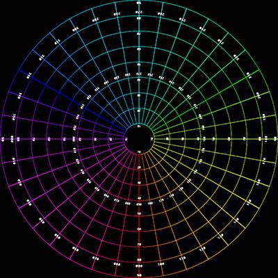 Sample input fisheye image |
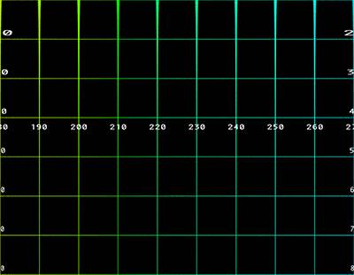 downfish2pano -a 3 -v 10 80 -t 0 90 |
Front pointing fisheye to panoramic warping
Software: frontfish2pano
In this case the fisheye is pointing horizontally, as such a traditional panoramic image is limited to half the normal horizontal extent.
Usage: frontfish2pano [options] fisheyeimage
Options
   -w n     panoramic image width, default = 600
   -h n     panoramic image height, default = 300
  -ap n     vertical aperture of panoramic, default = 100
  -af n     aperture of fisheye (degrees), default = 180
  -cf x y   center of the fisheye image, default is image center
   -r n     radius of the fisheye image, default is half the image width
  -fa n     angle for non level fisheye, default = 0
   -a n     antialiasing level, default = 1 (no antialising)
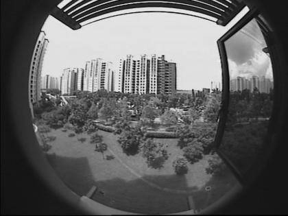 Input fisheye |
Default settings.
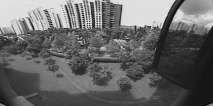 frontfish2pano -a 3 -cf 430 240 -r 330 |
Correct for the fact that the camera is not quite horizontal, this is the reason the vertical structure doesn't appear vertical in the panoramic images.
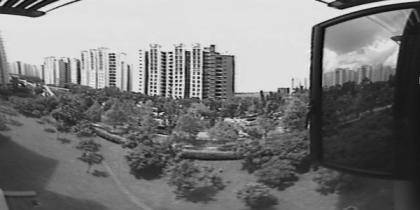 frontfish2pano -a 3 -cf 430 240 -r 330 -fa -20 |
Set the vertical aperture of the panoramic.
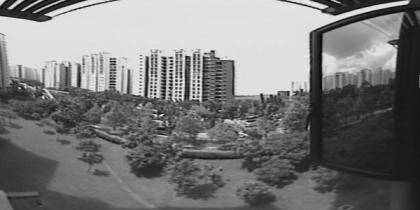 frontfish2pano -a 3 -cf 430 240 -r 330 -fa -20 -ap 110 |
Set the angle of the fisheye, this example is slightly less than 180 degrees.
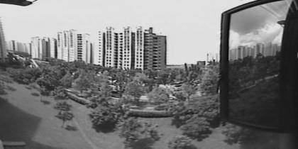 frontfish2pano -a 3 -cf 430 240 -r 330 -fa 20 -ap 110 -af 170 |
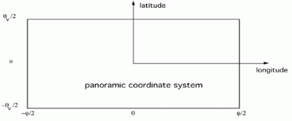
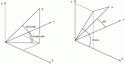
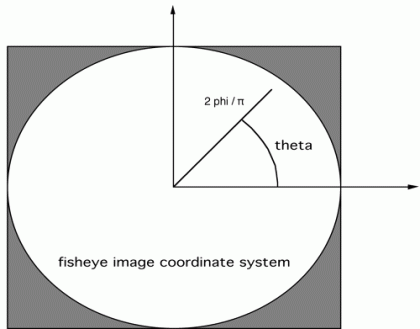
The coordinate system for fisheye and panoramic system is shown below.
Fisheye to spherical (partial) map
Software: fish2sphere
January 2005
Usage: fish2sphere [options] tgafile
Options
   -w n     sets the output image size, default = 4*inwidth
   -a n     sets antialiasing level, default = 1 (none)
   -r n     fisheye radius
  -fa n     fisheye aperture (degrees)
   -c x y   fisheye center, default is middle of image
Input fisheye image
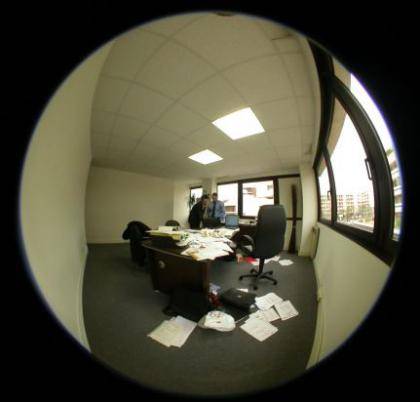
Default settings
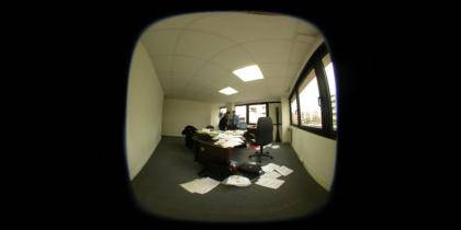
Set correct radius
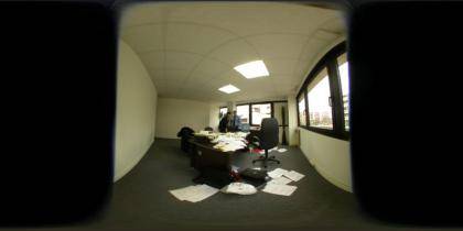
Specify fisheye center
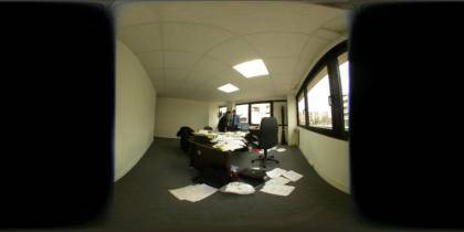
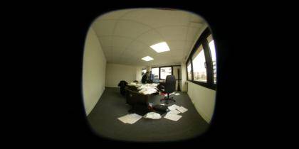
Set fisheye aperture
This can be readily computed in the OpenGL Shader Language, the following example was implemented in the Quartz Composer Core Image Filter.
// Fisheye to spherical conversion
// Assumes the fisheye image is square, centered, and the circle fills the image.
// Output (spherical) image should have 2:1 aspect.
// Strange (but helpful) that atan() == atan2(), normally they are different.
kernel vec4 fish2sphere(sampler src)
{
 vec2 pfish;
 float theta,phi,r;
 vec3 psph;
 float FOV = 3.141592654; // FOV of the fisheye, eg: 180 degrees
 float width = samplerSize(src).x;
 float height = samplerSize(src).y;
 // Polar angles
 theta = 2.0 * 3.14159265 * (destCoord().x / width - 0.5); // -pi to pi
 phi = 3.14159265 * (destCoord().y / height - 0.5); // -pi/2 to pi/2
 // Vector in 3D space
 psph.x = cos(phi) * sin(theta);
 psph.y = cos(phi) * cos(theta);
 psph.z = sin(phi);
 // Calculate fisheye angle and radius
 theta = atan(psph.z,psph.x);
 phi = atan(sqrt(psph.x*psph.x+psph.z*psph.z),psph.y);
 r = width * phi / FOV;
 // Pixel in fisheye space
 pfish.x = 0.5 * width + r * cos(theta);
 pfish.y = 0.5 * width + r * sin(theta);
 return sample(src, pfish);
}
The transformation can be performed in realtime using warp mesh files for software such as warpplayer or the VLC equivalent VLCwarp. A sample mesh file is given here: fish2sph.data. Showing the result in action is below.
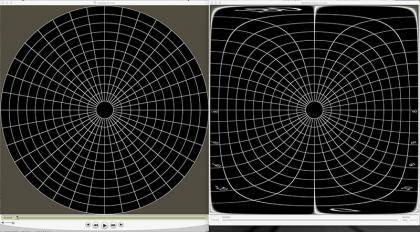
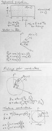
The maths is as folows.
Deriving a panoramic image from 4 fisheye images (Historical interest only)
February 2005
The following is an exercise to create panoramic images from a filmed fisheye movie. The fisheye filming was performed with the camera orientated in 4 positions, namely 90 degree steps, about 3 minutes were shot at each position. The scene was very dynamic, during the 12 minutes the lighting conditions were changing significantly as clouds passed over the sun. Additionally people were walking around the scene.
Fisheye pieces
 Fisheye set 1
|
 Fisheye set 2 |
Two sets of 4 fisheye images were acquired, the first set had as few people as possible in shot, the second had a number of people within each shot. Note these images are not close to each other in time, in general there was at least 3 minutes between each fisheye. The only criteria used when choosing the fisheye images was to choose images with similar lighting conditions.
Panoramic Pieces
 Panoramic pieces, set 1
|
 Panoramic pieces, set 2 |
The first stage is to turn the fisheye pieces into their corresponding panoramic sections. The complete panoramic is then formed by overlapping these four panoramic pieces and editing the result to remove discontinuities and inconsistencies between the pieces. Care needs to also be given to the left and right edge which also needs to match, this is can be achieved by adding the left most image after the right most image (or visa versa), with careful editing this will give a perfect seam (don't change the colour space of the left and right most image!).
Panoramic images
 Panoramic 1
|
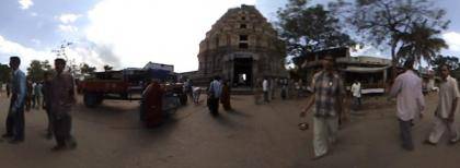 Panoramic 2 |
QuickTime VR
 QuickTime VR 1 |
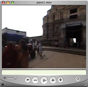 QuickTime VR 2 |
标签: fisheye
评论:
天气
分类
标签
存档
- 2024年3月(1)
- 2024年2月(1)
- 2023年8月(1)
- 2023年7月(1)
- 2023年5月(1)
- 2022年9月(1)
- 2022年8月(1)
- 2022年1月(2)
- 2021年10月(1)
- 2021年7月(1)
- 2020年9月(1)
- 2020年8月(1)
- 2020年7月(1)
- 2020年6月(2)
- 2020年5月(1)
- 2019年10月(1)
- 2019年9月(2)
- 2019年7月(1)
- 2019年1月(4)
- 2018年12月(1)
- 2018年11月(1)
- 2018年10月(5)
- 2018年8月(2)
- 2018年7月(5)
- 2018年6月(2)
- 2018年4月(1)
- 2018年2月(1)
- 2017年12月(2)
- 2017年11月(1)
- 2017年10月(4)
- 2017年9月(3)
- 2017年8月(2)
- 2017年5月(2)
- 2017年4月(7)
- 2017年2月(1)
- 2016年12月(1)
- 2016年11月(2)
- 2016年10月(3)
- 2016年6月(2)
- 2016年3月(1)
- 2016年1月(2)
- 2015年12月(3)
- 2015年11月(3)
- 2015年10月(1)
- 2015年9月(1)
- 2015年8月(2)
- 2015年7月(2)
- 2015年5月(1)
- 2015年4月(1)
- 2015年2月(1)
- 2015年1月(1)
- 2014年12月(4)
- 2014年11月(1)
- 2014年10月(1)
- 2014年8月(4)
- 2014年7月(2)
- 2014年6月(1)
- 2014年2月(2)
- 2014年1月(2)
- 2013年12月(26)
- 2013年10月(2)

 浙公网安备 33010602008237号
2019-09-24 17:49
我们希望尝试将其用于实时调查360摄像机到3D空间的管线